
Designcenter Solid Edge Model Based Definition fact sheet
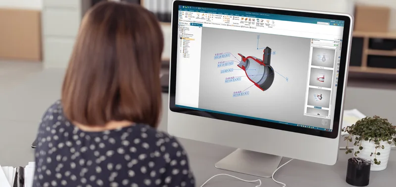
Put dimensions, tolerances and notes on the 3D model so downstream teams work without 2D drawings.
This three-page fact sheet describes the Model Based Definition add-on for Designcenter Solid Edge, which places the information needed for manufacturing directly on the 3D model. It explains how annotated models and 3D PDF output can replace or reduce the traditional pairing of a 3D model with a 2D drawing that has to be interpreted.
What the document covers
- Complete digital definition of parts and assemblies using product and manufacturing information (PMI) and existing model views
- AI-powered automatic 2D drawing generation with view placement, dimensioning and template selection
- Template-based 3D PDF publishing from the drafting environment, with customisable parts lists, render modes and optional password protection
- PMI import and export through STEP AP242, which also supports long-term archiving (LOTAR), plus JT, NX, DXF and DWG output
- Compliance with standards such as MIL-STD-31000B, ASME Y14.41, ISO 16792, ISO 1101, GB/T 24734 and ISO 21920-1 surface texture symbols
- Links to Solid Edge CAM Pro and additive manufacturing applications, and minimum system requirements
Who it is for
Relevant to design engineers, manufacturing and quality engineers, and supply chain teams that exchange technical data with suppliers who may not use the same CAD software.
Related product
 Designcenter Solid EdgeMechanical and electrical design for small and mid-size teams, with synchronous technology.See the product
More in the Knowledge Center


Have a project in mind?
Tell us what you are building and a NomuTech engineer will get in touch.