
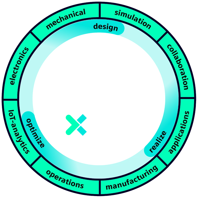
Designcenter Solid Edge PCB Collaboration fact sheet
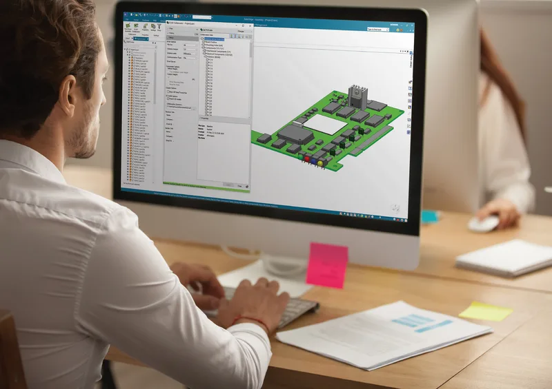
Exchange board outlines and component placement between Solid Edge and your ECAD system.
A three-page fact sheet on Designcenter Solid Edge PCB Collaboration, which connects electrical (ECAD) and mechanical (MCAD) design so that each engineer can stay in their own tool. It explains how printed circuit board and enclosure data are exchanged, reviewed and synchronised during the development of electromechanical products.
What the document covers
- Bi-directional exchange in the incremental design exchange (IDX) format, with support for IDX 2.0 and 3.0, and why this sends less unnecessary data than the older IDF format, which helps protect intellectual property
- Automatic alignment and mapping of 3D models when used with Siemens PADS Professional or Xpedition
- Replacing 2.5D component representations with 3D models from the included library, and checking ECAD and MCAD interferences in a true 3D view
- A pathfinder that sorts board components by type, such as cutouts, keep-outs and plated or non-plated mounting holes
- Import of copper layout data from the electrical side as sketches
- Guided change proposal, acceptance and synchronisation steps with notes and comments, in real time or batch mode through a shared directory or Dropbox
Who it is for
Mechanical engineers designing enclosures and electrical engineers laying out boards, especially where the work is split across companies or time zones.
Related product
 Designcenter Solid EdgeMechanical and electrical design for small and mid-size teams, with synchronous technology.See the product
More in the Knowledge Center


Have a project in mind?
Tell us what you are building and a NomuTech engineer will get in touch.