
Designcenter Solid Edge Piping Design fact sheet
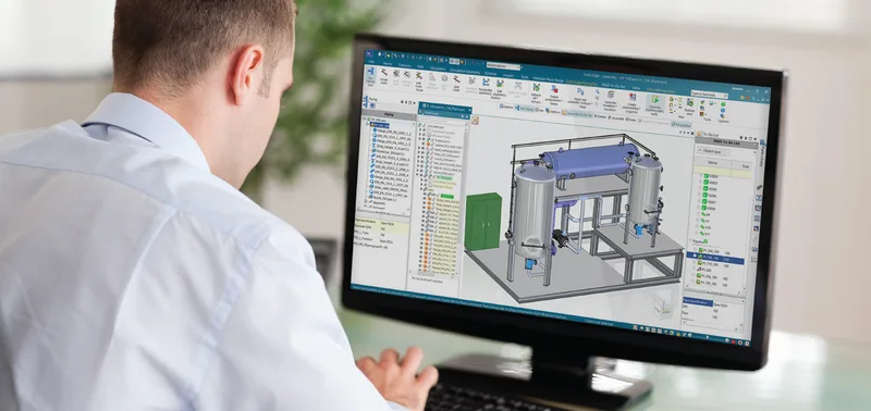
Piping design for skids, plant modules and machines, with standard components and isometrics.
This two-page fact sheet covers Designcenter Solid Edge Piping Design, a module for building 3D pipe systems inside Solid Edge assemblies, with modular plant design as the main use. Pipe specifications drive the automation, so the software checks parameters and places compatible components as routes are drawn or generated.
What the document covers
- Specification tables with project-specific parameters and plausibility checks, such as minimum and maximum pipe lengths for connections
- Route creation by drawing 3D lines or by automatically generating a complete specification-driven system, then editing, splitting, extending or shortening routes
- Automatic placement of elbows, tees, weldolets, flanges and gaskets, including fittings for non-round ducts such as cable ducts and ventilation
- 3D sketch tools with commands like auto route and edit route, and a basic engineering mode for rough early layouts with detail added later
- A 3D standard parts library, report generator, automatic bill of materials and isometric drawings for manufacturing
- Integration with Designcenter Solid Edge P&ID Design, including placing P&ID-defined features in the 3D model and cross-highlighting between the two
Who it is for
Designers and plant engineers working on skids, process plant modules and machines with integrated piping, who want to move from P&ID to a 3D pipe model and manufacturing isometrics in one environment.
Related product
 Designcenter Solid EdgeMechanical and electrical design for small and mid-size teams, with synchronous technology.See the product
More in the Knowledge Center


Have a project in mind?
Tell us what you are building and a NomuTech engineer will get in touch.