
Designcenter Solid Edge Wiring and Harness Design fact sheet
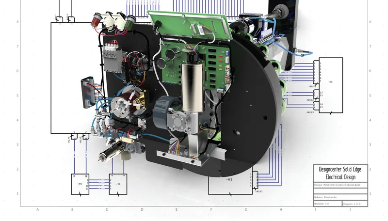
Wiring diagrams and 3D harness design that stay in step with the mechanical product.
This five-page fact sheet covers Designcenter Solid Edge Wiring and Harness Design, two modules for electrical design that work alongside Solid Edge mechanical CAD. It explains how wiring diagrams, harness drawings and the 3D mechanical model share data, so electrical and mechanical engineers can work in parallel and resolve space, clash and routing questions early.
What the document covers
- Solid Edge Wiring Design: electrically intelligent symbols, automated part selection, design rule checks and live display of voltages and currents to catch short circuits and check wire and fuse sizes
- Industrial control panel layout with DIN rails, wire ducts, terminal strip tables and autorouting of signal paths
- Solid Edge Harness Design: harness and formboard drawings, automatically populated connector and wire tables, and a parts selector for terminals, seals and wires
- Cross-probing between ECAD and MCAD, so changes such as wire colour appear in both domains
- Manufacturing reports, BOMs and costings, plus IEC and ANSI symbol libraries
- Teamcenter integration with BOM transfer, requirement linking and part synchronisation through Active Workspace
Who it is for
Useful for electrical and mechanical engineers in machinery, control panel and wire harness work, and for manufacturers who build harnesses in-house or to print.
Related product
 Designcenter Solid EdgeMechanical and electrical design for small and mid-size teams, with synchronous technology.See the product
More in the Knowledge Center



Have a project in mind?
Tell us what you are building and a NomuTech engineer will get in touch.